

Dam break analysis software free download - mine, not
The Open Civil Engineering Journal
3. RESULTS AND DISCUSSIONS
3.1. Analyzing Water Level Variations
Based on Analytical Ritter Solution, the water level profile variations are calculated by Eq 5:
 | (5) |
Where X and Z are the spatial dimensionless coordinates defined as X = x/h0 and Z = h/h0 . Where, x is the distance between a point in the flume and the beginning of the flume (gate), h0 is the initial level of water in the reservoir and h is the water level variations. The time dimensionless parameter is also T=t (g/h0 )0.5 that t is the time and g is the acceleration of gravity.
Fig. (2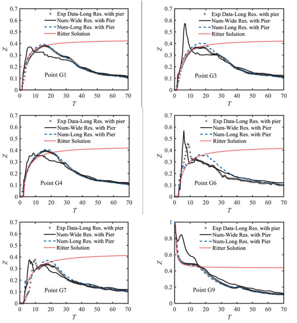 ) shows a comparison between the three-dimensional numerical model for both long and wide reservoirs, Ritter analytical solution and experimental data for variations in water level at the points G1, G3, G4, G6, G7 and G9. In these figures, the Z dimensionless values vs. T are plotted.
Table 3 presents the average difference between the experimental tests, 3D numerical model and Ritter's analytical solution for the long reservoir. Accordingly, within the range of T=0 to T=20, the water level from the experimental test is comparable well with Ritter's analytical solution. After this range, the water level variations have a decreasing trend due to the reservoir drainage while this trend is not observed in Ritter's analytical solution because the reservoir is assumed as infinite. Comparison of water level variations between the three-dimensional numerical model and the Ritter's analytical solution at the points between the dam (gate) and the pier i.e. points G1 and G3 in a downstream channel connected to long reservoir shows a small difference with the experimental data (about 8-12%). The reason for such low difference is that the super-critical flow created by the dam break in this area is parallel to the reservoir flow and there is no change in water path and complicated flow. Thus, the flow is one-dimensional and the three-dimensional numerical model and the analytical solution have close accuracies and are in appropriate agreement with experimental values.

Average water level difference between experimental data, numerical simulation and Ritter’s analytical solution results for long reservoir.
 | Fig. (2) Comparison between 3D numerical simulations with Ritter’s analytical solution and experimental values at different points for long and wide reservoirs. |
The numerical results at points G1 and G3 in the downstream channel of the wide reservoir indicate that the water level reaches its maximum value faster than similar points of the long reservoir. The reason for the maximum water level and faster attenuation of these points in the wide reservoir compared to the long reservoir is the formation of cross-waves in the wide reservoir's downstream, which is directly related to the reservoir geometry. However, such flow was not observed in the long reservoir and this is mainly due to the alignment of the reservoir and the downstream channel. Besides, fluctuations at the downstream water level are due to the reservoir geometry. After a sudden opening of the gate, surges are created and due to the short reservoir length, these waves can go forward and backward across the reservoir. Nevertheless, these waves are depreciated throughout the reservoir. The average difference between the numerical values obtained between the long and wide reservoirs at G1 and G3 points is 11 and 14%, respectively. Until 2 seconds after opening of the gate, the water level of the wide reservoir is higher than the long reservoir. Between 2 and 6 seconds, due to a faster attenuation of water level in the wide reservoir, the water level in the long reservoir is higher and after six seconds, the two reservoirs reach the same level. Comparison of water level variations between the three-dimensional numerical model and Ritter's analytical solution at the points between the dam (gate) and the pier i.e. points G6 and G7 for long reservoir indicate a significant difference between the values of the 3D numerical and experimental model due to the formation of the wake vortices. The range of differences is about 18 to 24% (Table 3). A similar trend takes place in the wide reservoir at the G6 and G7 points, except that due to the simultaneous effect of the cross-waves and wake vortices in the wide reservoir downstream channel, the intensity of the water level variations in wide reservoir is higher at the initial moments after the dam break. Moreover, at the inside points of the long reservoir (point G9) the water level difference between the numerical model and experimental data are not significant, which indicates high accuracy of numerical simulation at these points. The reason is that the flow conditions in the inside points of the reservoir are sub-critical causing one-dimensional flow to dominate those points. In the wide reservoir, the water level has a sharp drop in the inside point of reservoir right after opening the gate. After this sharp drop, the water level water level immediately increases and reaches its maximum and then decreases again. The reason for the increase in water level after a sudden drop is that the negative wave entering the wide reservoir reflects after colliding with the lateral walls of the reservoir and moves towards the gate. This reflected flow is fast and intense at the initial moments after opening the gate and collides at the G2 point, which increases in the water level at this point. Over time, the intensity of the reflected flow from the lateral walls reduces and causes small fluctuations in water level. The water level at the G9 point in a wide reservoir is 21% higher than the same point in the long reservoir on average.
3.2. Analysis of Velocity Profile Variations
Fig. (3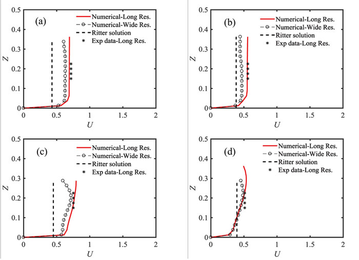 ) shows the distribution of the velocity obtained by 3D numerical model and the Ritter’s analytical solution at the flow depth in vs. the experimental values for long and wide reservoirs. The relative difference between each method with experimental data for long reservoir is presented in Table 4. The curves in Fig. (3
 ) are mapped as dimensionless at points G2 and G6. In these diagrams, the dimensionless parameters U and Z are defined as Z = h / h0 , where u is the flow velocity in the direction x, h0 is the initial level of water in the reservoir, h is the depth of flow and g is the acceleration of gravity. Eq. (6) is also used to calculate U by Ritter's analytical solution:
 | Fig. (3) Comparing in depth velocity distribution using experimental results and numerical and analytical models for long and wide reservoirs at point G2 (a) t=2s and (b) t=4s and point G6 (c) t=2s and (d) t=4s. |

Percentage of difference between in depth velocity distributions obtained from numerical and analytical models and experimental results for long reservoir.
 | (6) |
Where X, T and U are the dimensionless spatial, time and velocity coordinates defined as X = x / h0 , T = t (g/h0 ) 0.5 and. Where x is the distance between the point in the flume from the beginning of the flume (gate), u is the flow velocity in the x-direction, t denotes time and g is the acceleration of gravity.
Fig. (3 ) shows that in Fluent model, the velocity variations start from zero on the bed and trend to a certain amount away from the wall, while the velocity value is assumed to be uniform in depth in Ritter’s analytical solution. According to Table 4, at t = 2s and t = 4s at G2 and G6, the highest and the lowest difference is related to the Ritter’s solution and the 3D numerical model for long reservoir, respectively. The reason for such difference between Ritter’s solution and the experimental data (at time t = 2s, point G2) is that Ritter’s analytical solution is mainly valid for the points located on the central line of the flume, and the G2 point is not on the central line. For point G6, although this point is located on the central line, the flow is no longer one-dimensional due to the formation of wake vortices. Accordingly, since Ritter’s solution is mainly valid in one-dimensional state, the results of this model are different from the experimental values. The difference between Ritter’s analytical solution and the experimental values at t = 4s is less than t = 2s. This is due to the decrease in flow variations confirming the one-dimensional flow state. The velocity distribution from the 3D model at the depth of flow in the channel connected to the wide reservoir shows that at t=2 and 4 seconds after opening the gate, the wide reservoir's velocity at points G2 and G6 is lower than the same values in the long reservoir. This is mainly due to the inflow from the sides to the downstream channel and the creation of cross-waves in the wide reservoir. Moreover, at point G6, due to the interference of the cross-waves and wake vortices, uniform variations in the velocity distribution are reduced and they are accompanied by fluctuations in the flow depth.
3.3. Analysis of Pressure Variations
Fig. (4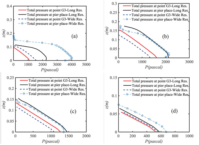 ) shows the pressure variations in the flow depth at the pier as well as point G3 in the channel downstream connected to the long and wide reservoirs at different times. Accordingly, in the long reservoir, the pressure on the pier increases at the initial moments after the dam break until it reaches its maximum value at t = 1s after opening the gate. This increase in pressure happens from the bottom of the channel to a flow depth of 0.1 m and pressure variation decreases after passing this depth. The reason for this pressure change is that at this time, the flow depth at the pier is about 0.1 m, and the horizontal component of the velocity along the flow is large at this time. Therefore, due to the collision of such a high-velocity flow with the pier and velocity conversion to the pressure (creating a stagnation point), it causes maximum pressure to a depth of 0.1 m from the bottom of the channel. Gradually, by decreasing the velocity component, the amount of pressure applied to the pier decreases, so that at t = 10s, the pressure changes occur with the same trend at the point G3 and the pier.
In the wide reservoir, the pressure variations around the pier and point G3 are similar to those in the long reservoir. At point G3, until the first 1.5s after opening the gate, pressure variations in the wide reservoir are greater than the similar value in the long reservoir. However, as illustrated in Fig. (4 ), this variation is intermittent over the time. In the wide reservoir downstream, the pressure variations created around the pier are greater than or equal to the observed value in the long reservoir.
3.4. Longitudinal Profile Variation of Water Level
Fig. (5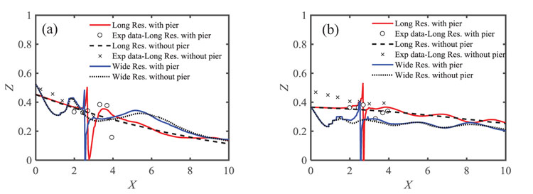 ) shows the comparison between numerical and experimental results of flood wave expansion at the downstream of long and wide reservoirs in dry bed conditions at t=2 and 4s.
 | Fig. (4) Distribution of pressure in depth using the results of the numerical model at point G3 and the bridge pier for long and wide reservoirs at (a) t = 1s, (b) t = 3s, (c) t = 5s and (d) t = 10s. |
 | Fig. (5) The variations in longitudinal profile of water level for long and wide reservoirs (a) t = 2s and (b) t = 4s. |
Fig. (5a ) shows the longitudinal profile of water level with and without pier at t = 2s for long and wide reservoirs. Accordingly, in the channel connected to the long reservoir and at a distance between the gate and 100cm farther (toward the pier), the water level variations for the pier presence are less than the absence of pier. The reason for this is the effect of the pier on the flow lines and the contraction of the flow in this range. After this distance, the changes in the water level in the model with pier are altered at the gate downstream compared to the model without pier. The sudden increase in water level is also observed within the distance of 100 to 150 cm from the gate. The main reason for sudden increase in water level is the existence of wake vortices at this distance. According to Fig. (5a
 ), at 0.5 m distance from the gate, the water levels profile of the wide reservoir has a sudden drop (for the cases with and without pier) while this water level has increased at a distance of 0.8 m from the gate. After this increase, the water level profile decreases until the flow hits the pier. As discussed above, the reason for this is that the transverse waves are reflected from the channel walls causing the formation of crests and troughs on the water level profile of this reservoir. Similar to the long reservoir, the wake vortices are created behind the pier and the water level increases compared to the absence of pier.
Fig. (5b ) shows the longitudinal profile of the water level for the conditions with and without the pier at t=4s for long and wide reservoirs. With respect to the water level, results indicate similar changes for both reservoirs compared to the previous state (t=2s) with the difference that over time the wake vortices rising towards the pier in nearby places and their intensity is reduced.
3.5. Flood Wave Motion
Figs. (6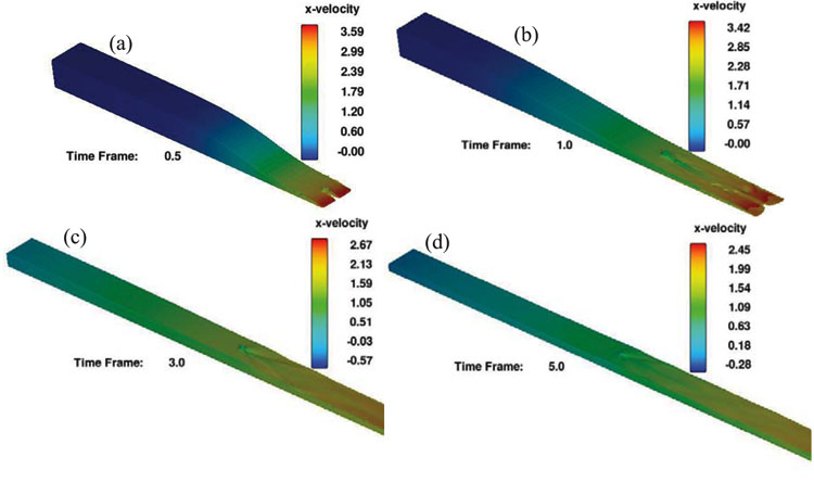 and 7
and 7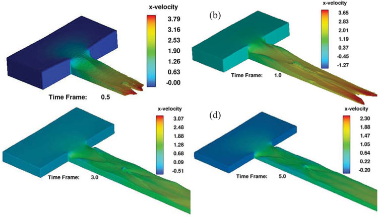 ) illustrate the flood wave motion at different times for the channel connected to the long and wide reservoirs. The backflow of the wave into the long reservoir is clearly visible in Fig. (6
 ). Based on the images, in the first moments after the dam break, the flood wave moves at a high velocity towards the downstream. Since the pier is located in the middle section of the channel connected to the long reservoir, it causes the waves to collide with the side walls and its re-entry into the channel, which results in transverse waves. In addition, because of the presence of pier, the wake vortices are clearly visible behind the pier. Over time, with the reservoir drainage, the intensity of the outflow is reduced and the wake vortices lose their effect. According to the images, the maximum longitudinal component of velocity decreases, which is due to the drainage of the long reservoir and the reduction of the level of water flow on the outlet. Fig. (7
 ) shows that the flood wave motion of the downstream channel connected to wide reservoir is different due to its geometry. Accordingly, in this reservoir, in the initial moments after the dam break, the flood wave moves with higher velocity but with the faster attenuation towards the downstream than the long reservoir. Due to the creation of cross-waves at the reservoir downstream, water level variations are fluctuating and these fluctuations continue throughout the channel. Due to the presence of the pier in the middle of the channel connected to the wide reservoir, the wake vortices behind the pier collide with cross-waves and make the flow more turbulent in this zone.
 | Fig. (6) Flood wave motion caused by dam break around the pier with long reservoir at (a) t = 0.5s, (b) t = 1s, (c) t = 3s and (d) t = 5s. |
 | Fig. (7) Flood wave motion caused by dam break around the pier with wide reservoir at (a) t = 0.5s, (b) t = 1s, (c) t = 3s and (d) t = 5s. |
CONCLUSION
In this research to investigate the effect of cylindrical piers on different flow patterns, the experimental study and 3D numerical simulation are conducted. A summary of results indicates that the existence of the pier in both long and wide reservoir conditions has no significant effect on water level variations inside the reservoir points and Ritter analytical solution values and 3D modeling results have no significant difference with the experimental results. The reason for this is the prevalence of sub-critical flow regime inside the reservoir. Besides, the reservoir shape has a significant impact on different flow patterns created at the gate downstream. Due to the alignment of the channel and the reservoir in the long reservoir, the dominant flow until its collision with the pier is 1D. Thus, one-dimensional solutions (including Ritter analytical solution) and 3D modeling at points G1 and G3 show no significant difference and fit well with the experimental data. After the passage of the flow through the pier, (points G6 to G8) due to the formation of the wake vortices, the flow loses the one-dimensional state and causes turbulence on the water surface. In this range, the Ritter analytical solution is far from the experimental data showing very low accuracy. Instead, the 3D numerical model provides acceptable results with a high accuracy in this range. In the wide reservoir, the cross-waves are formed at the reservoir downstream due to the effect of the reservoir geometry. From the beginning of the flow entry into the channel until its moment of collision with the pier, as well as passing through it, the flow loses its one-dimensional state. After the passage of flow through the pier, the severity of turbulence increases due to simultaneousness of the cross-waves and wake vortices. Hence, the Ritter analytical solution does not provide adequate answers in the entire channel while the three-dimensional numerical model has the appropriate accuracy. The velocity distribution obtained from the three-dimensional numerical model at the flow depth indicates that the velocity of points between the gate and pier is smaller in the channel connected to the wide reservoir than the ones for the long reservoir. This is mainly because of the entry of the flow from the sides into the downstream channel and the creation of cross-waves. After the flow passes through the pier, the velocity distribution of the points located in this zone in the channel connected to the wide reservoir is equal to or less than the long reservoir. However, because of the confrontation between the cross-waves and wake vortices, the in-depth velocity variations are not uniform and accompanied by fluctuations in the flow depth.

0 thoughts to “Dam break analysis software free download”